ANALOG COMMUNICATION TRAINER “GOTT-ACT-9329”
Technical Specifications
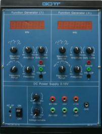
Function Generator (DC Power Supply & Function Generator, Optional Item, Code 500-107)
| Parameter | Value |
|---|---|
| Waveform | Sine, Triangle, Square, TTL Pulse |
| Amplitude | 10Vpp |
| Frequency Range, FG (I) | 0 – 10Hz, 0 – 100Hz, 0 – 1kHz, 0 – 10kHz, 0 – 100kHz |
| Frequency Range, FG (II) | 0 – 100Hz, 0 – 1kHz, 0 – 10kHz, 0 – 100kHz, 0 – 1MHz |
| Signal Output Ports | Two |
| Frequency Counter | Built-in 6-digit |
| Display | Two large 0.5″ LED displays |
| Protection | Overload Protection |
DC Power Supply (Optional Item, Code 500-107)
| Parameter | Value |
|---|---|
| Triple Bipolar Voltage Outputs | DC 0 – +/-15V, DC +/-5V, DC +/-12V |
| Operation | Constant & variable voltage operation |
| Ripple and Noise | Low |
Warranty: 2 Years
ANALOG COMMUNICATION TRAINER
Model Number: GOTT-ACT-9329
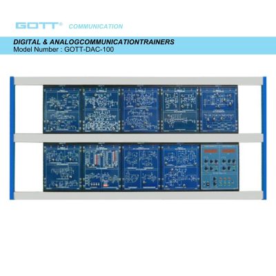
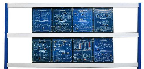
The GOTT-ACT-9329 Analog Communication Trainer is a laboratory training system from GOTT Communication, designed for the design and implementation of analog communication circuits. Its modules cover second order active filters and RF oscillators, AM and FM modulators and demodulators, DSB/SC and SSB modulators and demodulators, TDM and FDM multiplexers and demultiplexers, analog-to-digital and digital-to-analog converters, and frequency converters and signal recovery circuits. The trainer is supplied with a textbook that includes theoretical and practical details, and it requires only an oscilloscope to obtain measured results.
Key Features
- Textbook includes the theoretical and practical details.
- Textbook includes the expected results for reference.
- Problem discussion attached together with answers for instructor.
- Only need oscilloscope to obtain the measured results.
Experiments Included
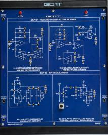
Second Order Active Filter & RF Oscillator (Code 600-101)
- Experiment 1: Second Order Active Low-pass Filter
- Experiment 2: Second Order Active High-pass Filter
- Experiment 3: Second Order Active Band-pass Filter
- Experiment 4: Second Order Active Band-stop Filter
- Experiment 1: Colpitts Oscillator
- Experiment 2: Hartley Oscillator
- Experiment 3: Crystal Oscillator
- Experiment 4: Voltage Controlled Oscillator
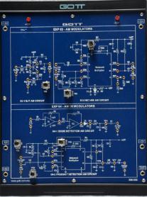
AM Modulator & AM Demodulator (Code 600-102)
- AM Modulator, Experiment 1: Transistor AM Modulator
- AM Modulator, Experiment 2: MC1496 AM Modulator
- AM Demodulator, Experiment 1: Diode Detector
- AM Demodulator, Experiment 2: Product Detector
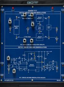
DSB-SC and SSB Modulator & Demodulator (Code 600-103)
- DSB-SC and SSB Modulator, Experiment 1: DSB-SC Modulator
- DSB-SC and SSB Modulator, Experiment 2: SSB Modulator
- DSB-SC and SSB Demodulator, Experiment 1: Product detector of DSB-SC Demodulator
- DSB-SC and SSB Demodulator, Experiment 2: Product detector of SSB Demodulator
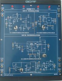
FM Demodulator & FM Modulator (Code 600-104)
- FM Demodulator, Experiment 1: MC4046 FM Modulator
- FM Demodulator, Experiment 2: LM565 FM Modulator
- FM Modulator, Experiment 1: MC4046 FM Demodulator
- FM Modulator, Experiment 2: LM566 FM Demodulator
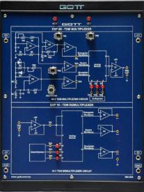
TDM Multiplexer & TDM Demultiplexer (Code 600-105)
- TDM Multiplexer, Experiment 1: Waveform Generator
- TDM Multiplexer, Experiment 2: TDM Multiplexer
- TDM Demultiplexer, Experiment 1: TDM Demultiplexer
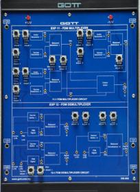
FDM Multiplexer & FDM Demultiplexer (Code 600-106)
- FDM Multiplexer, Experiment 1: FDM Signal Generator
- FDM Multiplexer, Experiment 2: DSB-SC Modulated Signal Generator
- FDM Multiplexer, Experiment 3: FDM Multiplexer
- FDM Demodulator, Experiment 1: FDM Demultiplexer
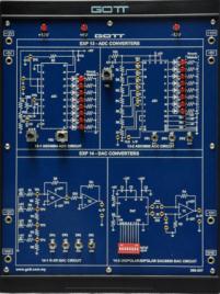
Analog-to-Digital Converter & Digital-to-Analog Converter (Code 600-107)
- Analog-to-Digital Converter, Experiment 1: ADC0804 Analog-to-digital Converter
- Analog-to-Digital Converter, Experiment 2: ADC0809 Analog-to-digital Converter
- Digital-to-Analog Converter, Experiment 1: R-2R Network DAC
- Digital-to-Analog Converter, Experiment 2: DAC 0800 Converter
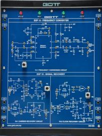
Frequency Converter & Signal Recovery (Code 600-108)
- Frequency Converter, Experiment 1: Frequency Multiplier
- Frequency Converter, Experiment 2: Up/Down Frequency Converter
- Signal Recovery, Experiment 1: Carrier Signal Recovery Circuit
- Signal Recovery, Experiment 2: Clock Recovery Circuit
Educational Objectives
- Design and implementation of second order active filters and RF oscillators.
- Design and implementation of AM and FM modulator and demodulator.
- Design and implementation of DSB/SC and SSB modulator and demodulator.
- Design and implementation of TDM and FDM multiplexer and demultiplexer.
- Design and implementation of frequency converter and signal recovery.