Air Flow Reaction Turbine – TH-3122
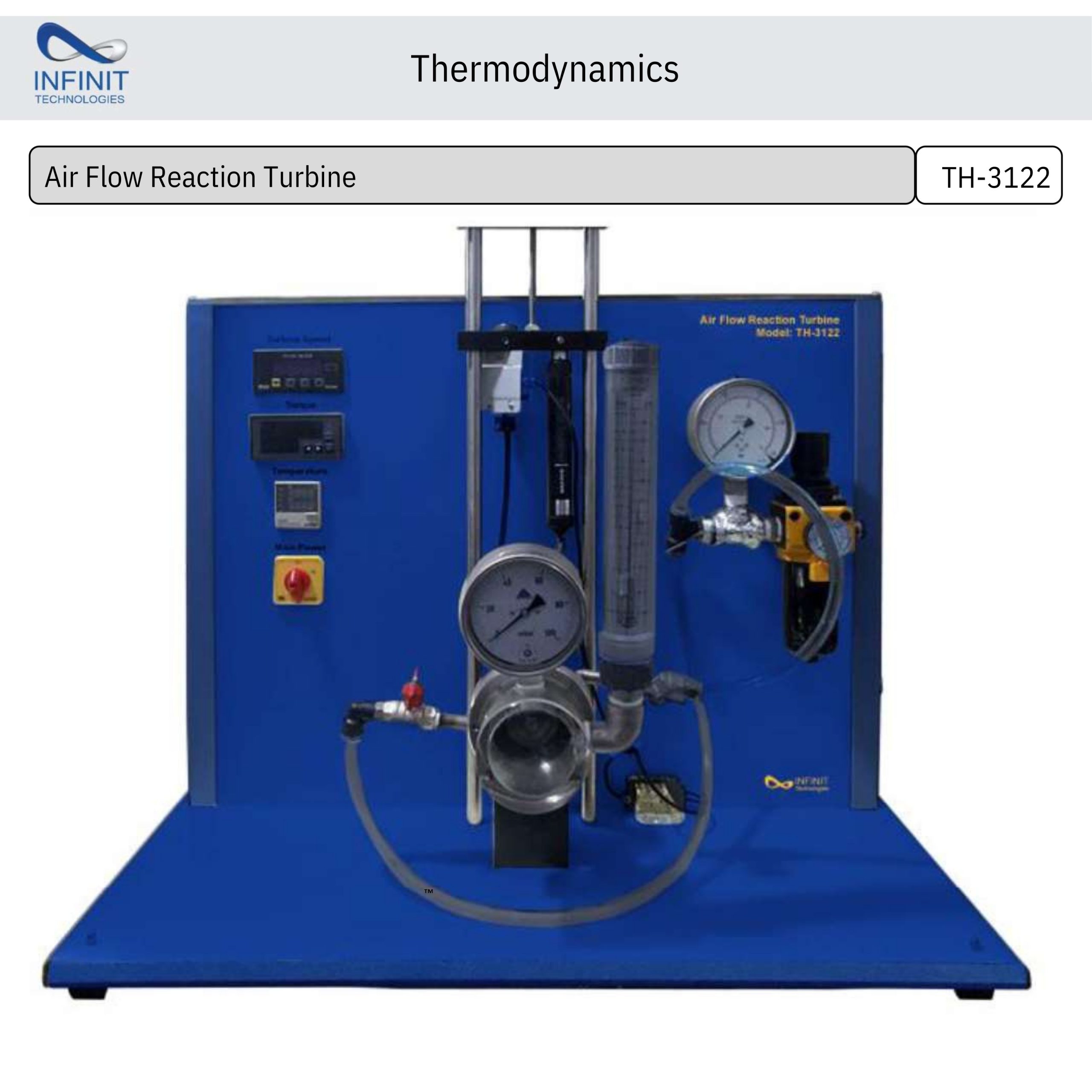
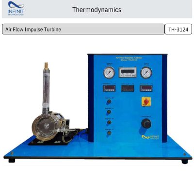
The Air Flow Reaction Turbine (TH-3122) is a laboratory demonstration unit designed to study the operating principles and performance characteristics of a reaction turbine using compressed air. The system operates as a standalone training apparatus and is ideal for engineering laboratories focusing on turbomachinery and fluid mechanics.
The turbine is driven by compressed air supplied from an external compressor. A transparent Plexiglass turbine housing allows students to clearly observe the airflow and rotor motion, helping them understand the reaction principle of turbine operation in real time.
To analyze turbine performance, the unit is equipped with a band brake braking system mounted on the turbine shaft. This mechanism enables accurate measurement of the load and torque applied to the turbine using an electronic dynamometer or spring balance. The turbine’s rotational speed is measured electronically through an inductive proximity switch, ensuring precise and reliable data collection.
An integrated interface allows users to display turbine speed and torque, while an optional data acquisition system with software enables measurement, processing, and storage of experimental data on a computer. The software is developed in the National Instruments LabVIEW environment and can run on any Windows-based PC.
This equipment is widely used in mechanical and energy engineering laboratories to demonstrate turbine performance analysis, efficiency calculations, and characteristic curve development.